A transfer switch wiring diagram manual serves as a comprehensive guide for installing and operating transfer switches safely. It provides detailed diagrams, instructions, and safety tips for both manual and automatic switches, ensuring seamless integration with electrical systems and generators for emergency power solutions.
1.1 Purpose of a Transfer Switch Wiring Diagram Manual
A transfer switch wiring diagram manual is designed to guide users through the safe and proper installation of transfer switches. It provides clear, step-by-step instructions and detailed diagrams to ensure correct wiring configurations. The manual helps users understand how to connect generators, electrical panels, and circuits effectively. It also highlights safety protocols to prevent electrical hazards. This resource is essential for both professionals and novices, ensuring compliance with electrical standards and regulations while maintaining system reliability and performance during power outages.
1.2 Importance of Proper Wiring Diagrams for Safety
Proper wiring diagrams are critical for ensuring safety during the installation and operation of transfer switches. They provide clear instructions to avoid electrical shocks, fires, and system damage. Incorrect wiring can lead to hazardous conditions, making it essential to follow detailed diagrams. These guides help users identify correct connections, voltage ratings, and grounding requirements. Adhering to wiring diagrams ensures compliance with electrical standards, protecting both people and property from potential risks associated with improper installations.

Types of Transfer Switches
Transfer switches include manual, automatic, and portable options, each designed for specific applications. Manual switches require user intervention, while automatic switches operate without manual input, ensuring seamless power transitions.
2.1 Manual Transfer Switches
A manual transfer switch requires physical operation to switch between power sources, offering a cost-effective solution for managing backup power. Ideal for portable generators, these switches allow homeowners to safely power essential circuits, such as refrigerators and furnaces, during outages. Proper installation is critical to ensure safety and functionality. Users must manually activate the switch, making it a straightforward option for those with basic electrical knowledge; Always follow the wiring diagram and safety guidelines to avoid risks and ensure reliable operation.
2.2 Automatic Transfer Switches (ATS)
An Automatic Transfer Switch (ATS) seamlessly switches between utility and generator power during outages, eliminating manual intervention. Ideal for standby generators, ATS ensures continuous power supply to critical circuits. Installation requires precise wiring to match voltage and current ratings, with a focus on safety and compliance. The ATS automatically detects power loss and transitions to the generator, making it a convenient and reliable solution for homeowners seeking uninterrupted power. Proper setup and regular maintenance are essential for optimal performance and longevity.
2.3 Portable vs. Installed Transfer Switches
Portable transfer switches offer flexibility, allowing easy relocation and connection to different generators or circuits. They are ideal for temporary or seasonal use, providing a cost-effective solution. Installed transfer switches, however, are permanently mounted, ensuring a reliable and seamless power transition. They are hardwired into the electrical system, offering higher safety and efficiency. Portable switches are simpler to set up but may lack the robust features of installed models. Both options require proper wiring and adherence to safety standards for safe operation.

Key Components of a Transfer Switch Wiring Diagram
A transfer switch wiring diagram includes hardware like switches and circuit breakers, wiring connections, load calculations, and safety guidelines. It ensures proper installation and operation.
3.1 Transfer Switch Hardware
Transfer switch hardware includes the physical components necessary for installation, such as the switch itself, circuit breakers, and load centers. Manual switches are often used for portable generators, allowing users to control specific circuits, while automatic switches integrate with standby generators for seamless power transitions. The hardware must be rated appropriately for voltage and current to ensure safety and efficiency. Proper selection and installation of these components are critical to avoid overloads and ensure reliable operation during power outages.
3.2 Wiring and Circuit Breakers
Wiring and circuit breakers are essential for safe and efficient transfer switch installations. Properly sized wires ensure reliable power transfer, while circuit breakers protect against overloads and short circuits. The wiring must be rated for the system’s voltage and current, with clear connections to the generator, transfer switch, and electrical panel; Circuit breakers should be selected based on the load requirements and installed in series to provide overload protection. Correct wiring practices and breaker configurations are critical to prevent electrical hazards and ensure seamless power switching.
3.3 Load Calculations and Ratings
Accurate load calculations are crucial for selecting the right transfer switch and ensuring safe operation. This involves assessing the total power requirements of all connected appliances and systems. The transfer switch must be rated to handle the maximum expected load, considering both voltage and current. Proper sizing prevents overheating and ensures reliable performance. Always consult the wiring diagram manual for guidance on calculating loads and selecting appropriately rated components to avoid undersizing or oversizing the equipment, which can lead to safety hazards or inefficiency. Proper sizing ensures safe and efficient power transfer during outages.
Safety Considerations for Transfer Switch Installation
Ensure proper voltage and current ratings, and always follow grounding and earthing requirements. Adhere to lockout/tagout procedures to prevent accidental power restoration. Consult local codes and manuals to guarantee compliance and safety during installation and operation of transfer switches.
4.1 Understanding Voltage and Current Ratings
Understanding voltage and current ratings is crucial for safe and proper transfer switch installation. Always match the switch’s voltage and current ratings to your generator and electrical panel. A 200A-rated switch is suitable for circuits with a 150A maximum breaker. Ensure the transfer switch can handle the generator’s maximum power output. Refer to the manual for specific ratings and compatibility. Proper alignment prevents overheating and ensures reliable operation. Always adhere to local electrical codes and manufacturer guidelines for optimal safety and performance.
4.2 Grounding and Earthing Requirements
Proper grounding and earthing are essential for the safe operation of transfer switches. Ensure the grounding wire is securely connected to both the generator and the electrical panel. This prevents electrical shocks and equipment damage. Verify the grounding system’s continuity using a multimeter. Always follow NEC guidelines for grounding to ensure compliance and safety. A well-grounded system protects against voltage surges and maintains reliable power transfer during outages. Use copper wires for grounding due to their excellent conductivity. Proper grounding ensures the system operates safely under all conditions.
4.3 Lockout/Tagout Procedures
Lockout/Tagout (LOTO) procedures are critical for ensuring safety during transfer switch installation and maintenance. Always disconnect power sources and verify de-energization using a multimeter. Apply locks and tags to prevent accidental energization. Use standardized tags indicating work in progress and ensure only authorized personnel remove them. Follow OSHA guidelines to protect technicians from electrical hazards. Proper LOTO ensures a safe working environment and prevents unexpected power restorations, safeguarding both equipment and personnel during servicing or upgrades.

Wiring Diagrams for Manual Transfer Switches
Manual transfer switch wiring diagrams provide step-by-step instructions for connecting generators to home electrical panels. They ensure safe power transfer and proper load management during outages.
5.1 Connecting the Generator to the Transfer Switch
To connect a generator to a manual transfer switch, start by identifying the generator’s wires: hot (black), neutral (white), and ground (bare or green). Refer to the wiring diagram provided in the manual for specific terminal connections on the transfer switch. Attach the hot wires to the designated “generator” terminals, the neutral wire to the switch’s neutral terminal, and the ground wire to the grounding terminal. Ensure all connections are secure and match the generator’s power rating to prevent overheating or electrical hazards. Finally, verify the connections by turning the generator on and testing the transfer switch operation.
5.2 Integrating with Home Electrical Panels
Integrating a transfer switch with your home’s electrical panel involves connecting the switch to specific circuits or the main breaker. Start by turning off the main power supply at the breaker. Connect the transfer switch’s output wires to the designated circuits in the panel, ensuring they match the load requirements. Verify the polarity of each wire to avoid electrical issues. Secure all connections tightly and double-check the wiring diagram for accuracy. Finally, test the system by switching between utility and generator power to ensure smooth operation and proper circuit prioritization.
5.3 Wiring for Multiple Circuit Loads
Wiring for multiple circuit loads requires careful planning to ensure proper power distribution. Identify the circuits you want to power, such as lights, appliances, and HVAC systems, and calculate their combined load. Use appropriately sized wires and circuit breakers to handle the total current. Connect each circuit to the transfer switch, ensuring they are correctly labeled and matched to their respective loads. Double-check the wiring diagram for accuracy and test the system to confirm all circuits function correctly when switching between utility and generator power.

Wiring Diagrams for Automatic Transfer Switches
Automatic transfer switches streamline the process of switching between utility and generator power, ensuring a reliable and seamless connection during power outages with detailed wiring guidance.
6.1 ATS Installation for Standby Generators
Installing an automatic transfer switch (ATS) for standby generators ensures seamless power transition during outages. The ATS is typically placed between the generator and the electrical panel. Proper installation involves matching the ATS voltage and current ratings to the generator and load requirements. It’s crucial to follow the wiring diagram to connect the utility and generator power sources correctly. Mounting the ATS near the electrical panel simplifies wiring and ensures compliance with safety standards. Testing the ATS operation before final installation guarantees reliable performance during power failures.
6.2 Configuring ATS for Different Load Priorities
Configuring an automatic transfer switch (ATS) for different load priorities ensures essential appliances receive power first during outages. Start by identifying critical loads like refrigerators and HVAC systems, which should be prioritized over non-essential ones. Use the ATS wiring diagram to connect these high-priority circuits first. If your ATS has a digital interface, set priorities through the menu; otherwise, connect circuits in order of importance. Ensure the generator’s capacity matches the total load to prevent overloading. Always follow the manufacturer’s guidelines for a safe and efficient setup.
6.3 Troubleshooting ATS Wiring Issues
Troubleshooting ATS wiring issues involves identifying common problems like power loss or incorrect transfer. Check for loose connections, faulty sensors, or incorrect wiring configurations. Ensure all wires match the diagram and verify the ATS is properly calibrated. Test the ATS by simulating a power outage to confirm smooth switching. If issues persist, consult the manual or contact a professional. Regular maintenance can prevent many wiring-related problems, ensuring reliable operation during emergencies.
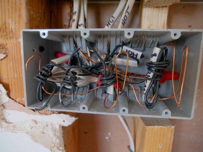
Common Symbols and Notations in Wiring Diagrams
Wiring diagrams use standardized symbols for components like switches, circuits, and wires; Color coding and notation systems help identify live, neutral, and ground connections, ensuring accurate installations.
7.1 Understanding Circuit Symbols
Circuit symbols are essential for interpreting wiring diagrams. Common symbols include circles for switches, lines for wires, and triangles for ground connections. These representations simplify complex electrical layouts, ensuring clarity. Color coding further aids in identifying live, neutral, and ground wires. Understanding these symbols is crucial for accurate installations and troubleshooting. A legend or key is often provided to decode symbols, making diagrams accessible to both professionals and DIY enthusiasts. Proper interpretation ensures safety and efficiency in transfer switch wiring projects.
7.2 Color Coding for Wires
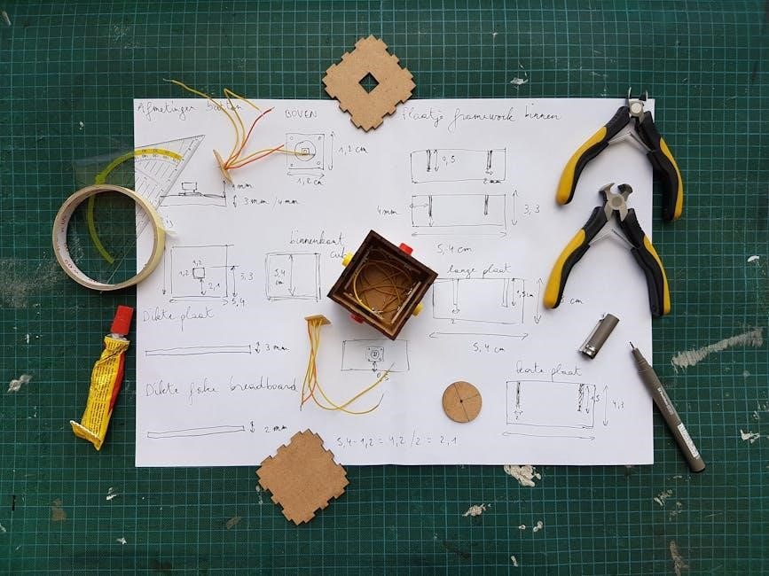
Color coding is a critical aspect of wiring diagrams, ensuring clarity and safety. Black wires typically represent hot lines, while white signifies neutral. Green or copper wires are reserved for grounding. Red wires often indicate secondary hot connections or switches. This standardized system aids in identifying wire functions at a glance, reducing errors during installation and troubleshooting. Proper adherence to color coding ensures compliance with safety standards and prevents potential hazards in transfer switch configurations.
7.3 Diagram Legend and Key
A diagram legend and key are essential for interpreting wiring diagrams. They provide explanations for symbols, abbreviations, and color codes used throughout the manual. Common symbols include circles for switches, lines for wires, and rectangles for electrical panels. The key helps users understand the meaning of each component, ensuring accurate installations. For example, a dashed line may indicate a control circuit, while a solid line represents a power connection. This reference guide is crucial for deciphering complex diagrams and ensuring safety during transfer switch installations.
Step-by-Step Installation Guide
This guide outlines the process for installing a transfer switch, from preparing the site to final testing. It ensures a safe and efficient setup for emergency power solutions.
8.1 Preparing the Site and Tools
Begin by selecting a suitable location for the transfer switch, ensuring it’s accessible and close to the electrical panel. Gather essential tools like screwdrivers, pliers, and wire strippers. Verify the compatibility of the transfer switch with your generator and electrical system. Shut off the main power supply before starting work. Wear safety gear, including gloves and goggles, to protect against electrical hazards. Ensure all components and wires are labeled correctly for a smooth installation process. Follow the manual’s guidelines to avoid errors and ensure compliance with safety standards.
8.2 Mounting the Transfer Switch
Mount the transfer switch in a location accessible and close to the electrical panel. Use a sturdy mounting bracket to secure it, ensuring it is level and properly aligned. Drill holes for screws, avoiding damage to surrounding surfaces. Tighten the mounting screws firmly to prevent movement. Ensure the switch is compatible with your electrical system and generator. Double-check the manual for specific mounting instructions and safety guidelines. Proper installation ensures reliable operation and compliance with electrical standards.
8.3 Connecting Wires to the Transfer Switch
Connect the wires to the transfer switch by matching the generator’s output wires to the corresponding terminals. Use the wiring diagram to identify hot, neutral, and ground wires. Ensure the black wire from the generator connects to the “hot” terminal on the switch. The neutral wire should be connected to the neutral terminal, and the ground wire to the grounding terminal. Tighten all connections securely. Turn off the generator before making connections and use a voltage tester to confirm power is off. Follow color coding for safe and accurate wiring. Double-check all connections to avoid short circuits or malfunction.
8.4 Testing the Installation
After connecting the wires, test the installation to ensure proper function. Use a multimeter to verify voltage levels between the generator and transfer switch. Activate the transfer switch and check if power transitions smoothly from utility to generator. Test all connected circuits to confirm they receive power. Ensure the generator operates under the expected load. Listen for unusual noises or vibrations. Verify that the transfer switch returns to utility power once the generator is turned off. This step ensures safe and reliable operation of your backup power system.
Maintenance and Troubleshooting
Regular maintenance ensures reliable operation; Inspect connections, clean contacts, and check for wear. Troubleshoot issues like faulty sensors or wiring problems promptly to avoid downtime.
9.1 Regular Maintenance Checks
Regular maintenance checks are crucial for ensuring the transfer switch operates efficiently. Inspect all connections and contacts for cleanliness and wear. Verify that all wires are securely attached and show no signs of damage. Check the circuit breakers and ensure they are functioning correctly. Schedule annual professional inspections to identify potential issues early. Refer to the wiring diagram manual for specific guidance tailored to your transfer switch model. Consistent upkeep prevents unexpected failures and ensures reliable power transfer during outages.
9.2 Common Issues and Solutions
Common issues with transfer switches include faulty sensors, loose connections, or worn contacts. If the switch fails to activate, check for tripped circuit breakers or blown fuses. For automatic models, ensure proper voltage sensing. Clean dirty contacts and tighten connections to resolve operational hiccups. If the transfer switch shows an error code, consult the wiring diagram manual for troubleshooting steps. Replacing worn-out components and ensuring proper grounding can prevent recurring issues. Always test the switch after repairs to confirm functionality.
9.3 Upgrading or Replacing Components
Upgrading or replacing components in a transfer switch requires careful planning and adherence to the wiring diagram manual. Ensure all new parts are compatible with the existing system. Start by powering off the circuit and disconnecting wires. Replace worn-out or outdated components, such as circuit breakers or switches, with rated equivalents. Refer to the manual for specific instructions and torque specifications. After installation, test the system to confirm proper operation. Regular upgrades can enhance performance and ensure long-term reliability of the transfer switch system.
A transfer switch wiring diagram manual is an essential resource for safe and efficient electrical system management. It ensures proper installation, operation, and maintenance of transfer switches, providing a reliable power solution during outages. By following the guidelines and diagrams, users can achieve optimal performance and compliance with safety standards, ensuring their electrical systems remain secure and functional under all conditions.
10.1 Summary of Key Points
A transfer switch wiring diagram manual is crucial for ensuring safe and efficient electrical system management. It provides detailed guidance on installing, operating, and maintaining transfer switches, whether manual or automatic. Key points include understanding wiring diagrams, selecting the right switch for voltage and current ratings, and adhering to safety protocols like proper grounding and lockout/tagout procedures. The manual also emphasizes load calculations, circuit breaker configurations, and regular maintenance to prevent faults. By following these guidelines, users can ensure reliable power during outages while minimizing risks of electrical hazards.
10.2 Final Safety Reminders
Always prioritize safety when working with transfer switches. Ensure proper grounding and earthing to prevent electrical hazards. Follow lockout/tagout procedures to avoid accidental power restoration. Verify voltage and current ratings match your system to prevent damage. Never overload circuits, and keep transfer switches away from flammable materials. Regularly inspect wiring and components for wear or damage. If unsure, consult a licensed electrician. Adhere to manufacturer guidelines and local electrical codes for a safe installation. Remember, safety is paramount to protect people, property, and equipment.
